WEEK
TEN
Make a Machine
Task for this week
Group Assignment
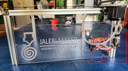
So In this week we have to design and make a machine which working based on CNC. So We decided to make a jalebi making machine. Jalebi is the nationalsweet dish. In India Jalebi is tradionally made by hand , so for this week we decided to make a Jaleni maker machine. We are two students at Vigyan Ashram
pabal .Pushkar Sooryvanshi and me. So we devided the work for this assignment. Pushkar have to arrange the material and take the resposibilities of assembly.
I take the responsibilty of designing and electronic assembly and programming.
To know more about the group assignment click here
Individual contribution
Designing process
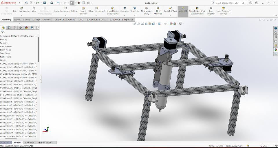
So I start the designing process for the machine. Firstly we have to make base of the machine. So we decided to make the base of the machine which will400mm in length and the 400mm width and we give the hieght of 200 mm to it. So for making this base we have to use V slot aluminium extrusion profile.
This extrusion profile is about 20mm*20mm in size.
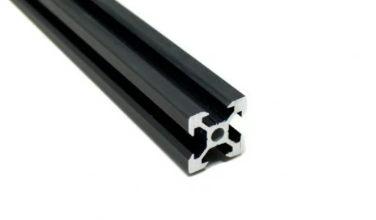
So I download the design file of this aluminium extrusion profile from GRABCAD and then start the assembly for the machine.
Before assembly I just modified the v slot extrusion size for the lenght, breadth and height of the machine. I am using the Solidworks Software for the
Design and assembly process.
I modified the v panel for lenght and breadth and then doing same process to design 200mm height v panel extrusion for the machine.
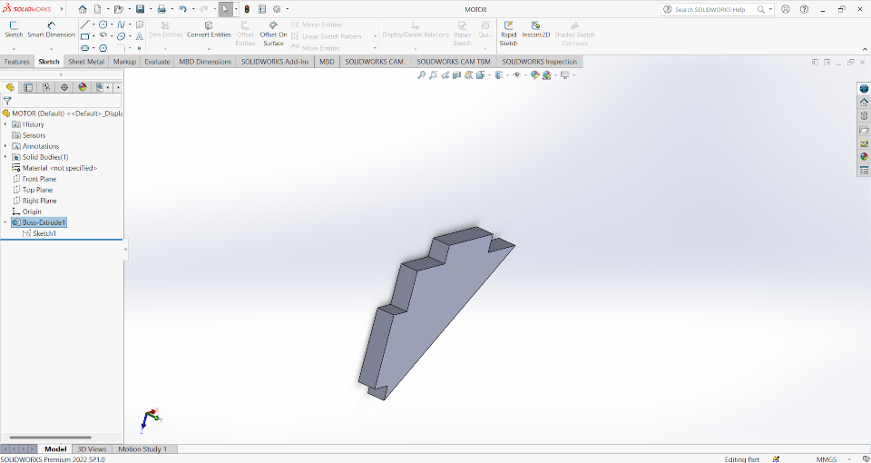
After that I design the connector for this v panel. So I take a real one and then measure its dimensions and designed them in software. This 90 degree
connector hold the all aluminium panel tightly.
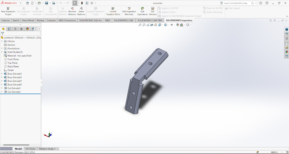
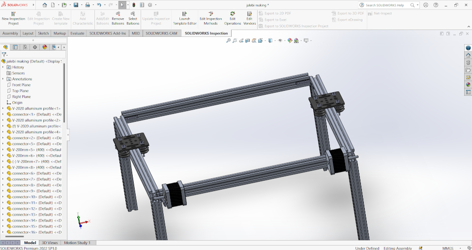
When I complete this design file I started the assembly process and assemble the aluminium panel with connectors and the base of the machine is ready
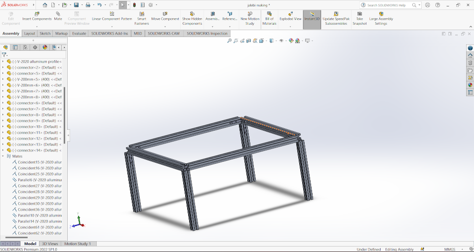
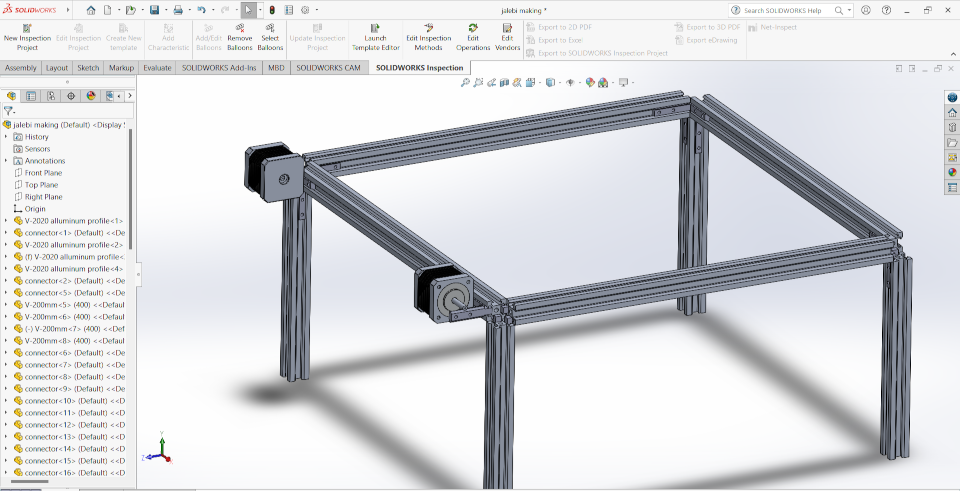
After That I am using a Nema17 motor design file which I download from GRABCAD. Now ro fit the motor with
this chasis of alumium I am using The connector. So I connected two connector at one side of the machine for the motor fitting.
After that I assembled the machine on the conectors
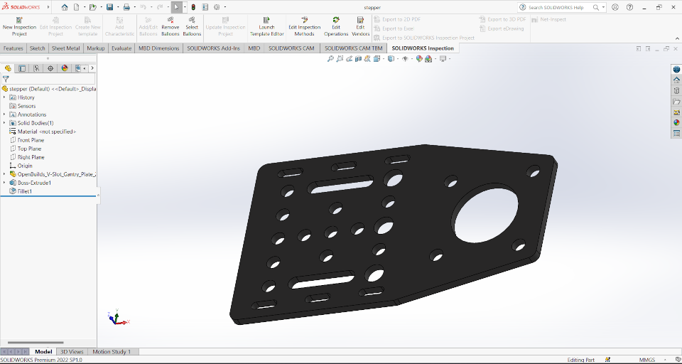
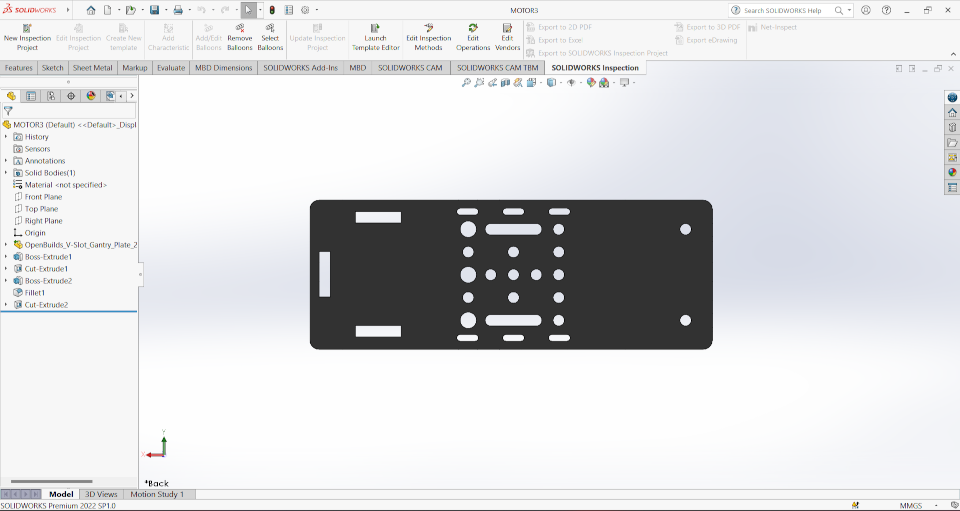
When the machine assembled then I am gonna use V slot gantry plate. This plate hold the wheel which roll on the aluminium panel and this also hold the
aluminium extrusion on it. It have many holes of different sizes holes on which we set the wheel and aluminium extruison on it. So I download the
design file of gantry panel of thickness 2mm and wheels for the movement from the GRABCAD. Then design a screw hollow cylindrical shape for the fitting of wheel on the gantry plate. Now this screw fitted on the gantry panel than we fit the
cylidrical hollow separator to the screw and then we fix assembled the wheel on it. We have to used separator to keep away wheel from the gantry panel.
After that I assembled all this thing together on the assembly of aluminium extrusion.
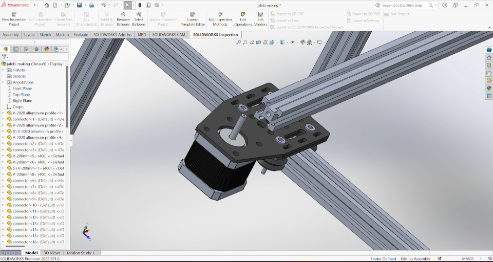
After that I modified the design of gantry plate. The first i designed the gantry palte to hold the nema 17 on it and another designed hold the pulley.
and this two design part I assemble on the gantry plate.
The below part is designed to hold the pulley and will assemble on gantry plate.
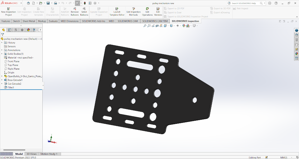
After the part assembly for the pulley holder and motor holder on the gantry plate. Now this gantry plate move only in one driection let for x axis only
So I assemble another aluminium extrusion on this gantry plate for the y axis movement.
After that I assembled the motor on motor holder which I design by doing modification in gantry plate
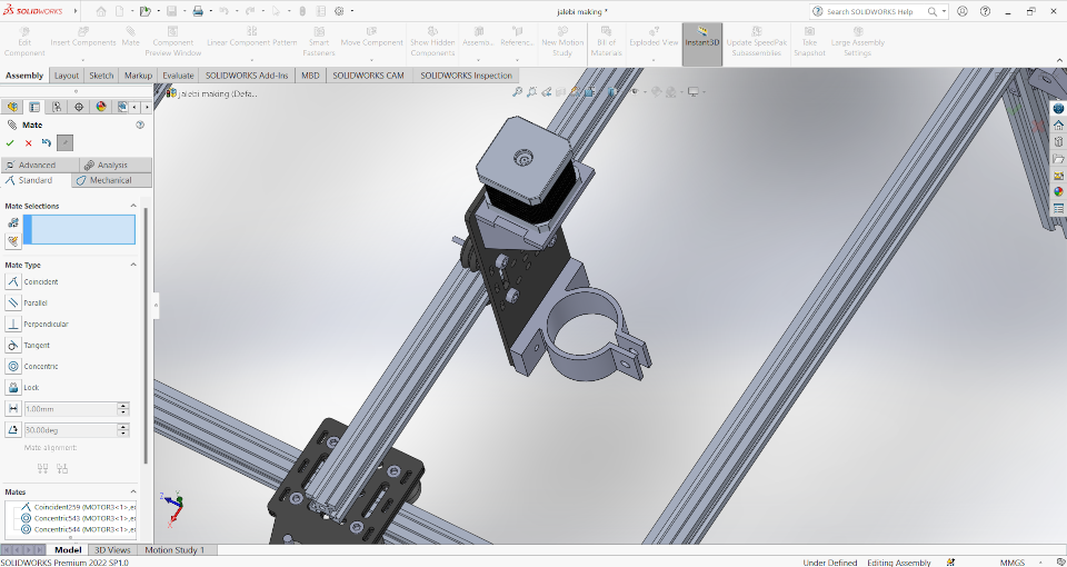
Now I modify the degine of gantry plate to hold the motor for the movement of z axis. It also hold the container of batter for the Jalebi making
Then I assembled the redesign gantry plate with wheel on the aluminium extrusion which is assembled on the motor and pulley holder part
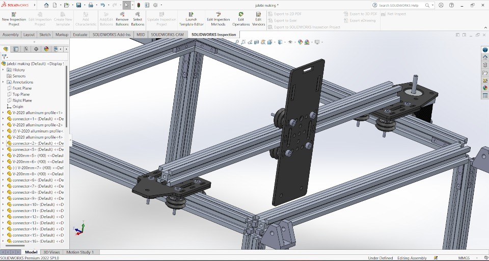
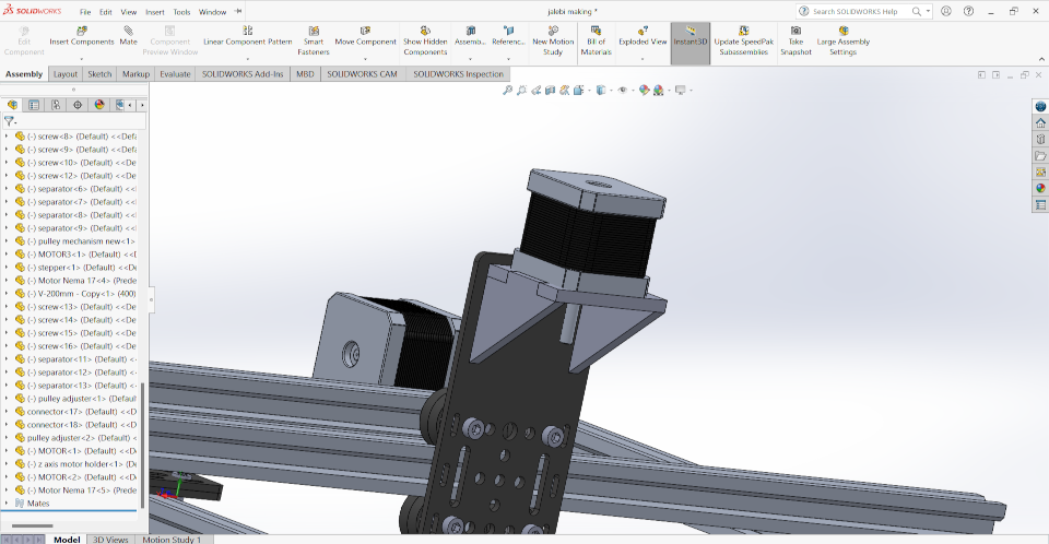
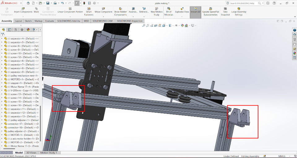
After that I design a Two new part on which we assemble the motor for the movement of z axis. and this two parts are given below-
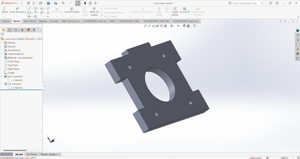
And then I assembled this parts on the machine
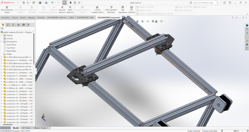
Now to provide movement to the x axis, we are used two motor. This motor are provide the motion by pulley belt. Both the end of the belt is connected
to gantry panel and then one side it connect with motor and another side we have to provide a pulley for the movement of belt. So at another side, I
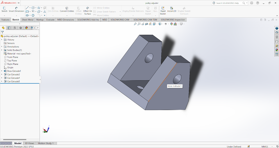
design a part which hold the pulley and assembled this part on both side.
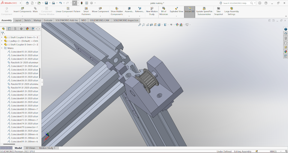
After That I download the design file of pulley fromGRABCAD and assembled on the machine assembly.
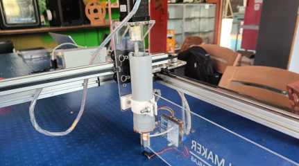
Then I designed the extruder part and extruder holder and then assebled them on the machine. The extruder will filled by jalebi making material
and it is pushed by the screw mechanism.
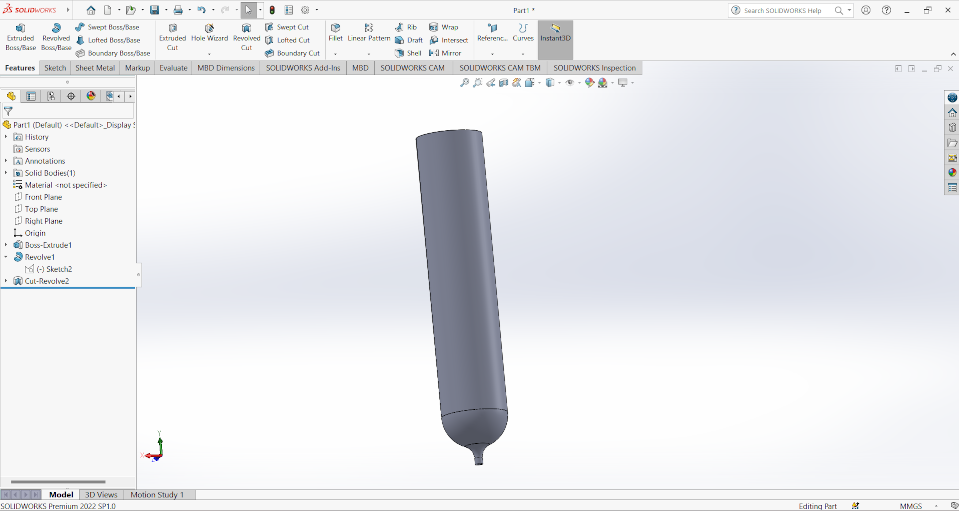
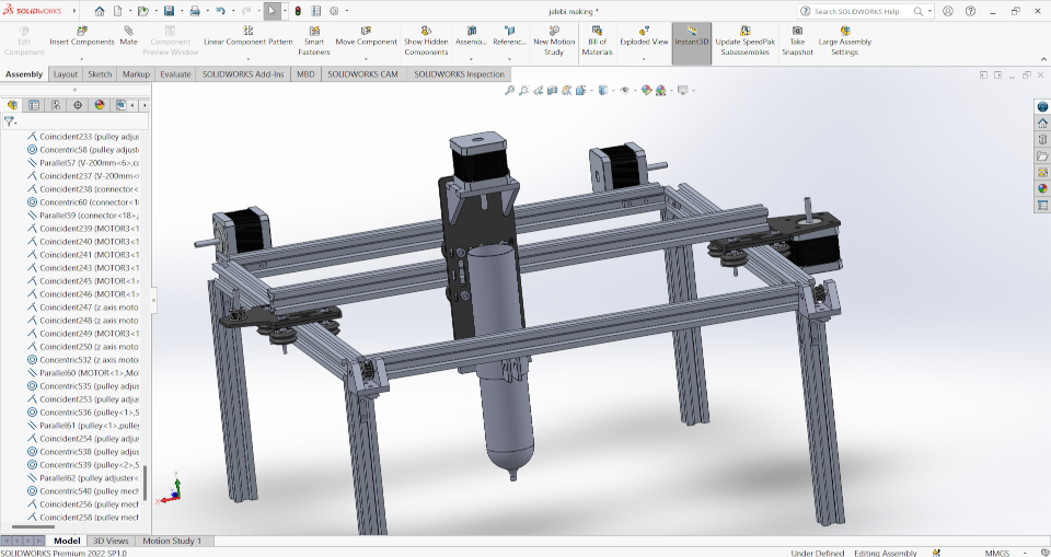
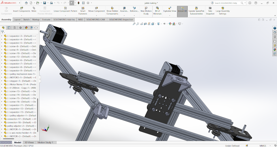
Now my design is ready. You can see the result-
After Designed I Started working on the Electronic Of the machine.
Electronics of the machine
After the designing part I have to reponsibility of electronics of the machines so we arranged all the component used for the machine.Component details
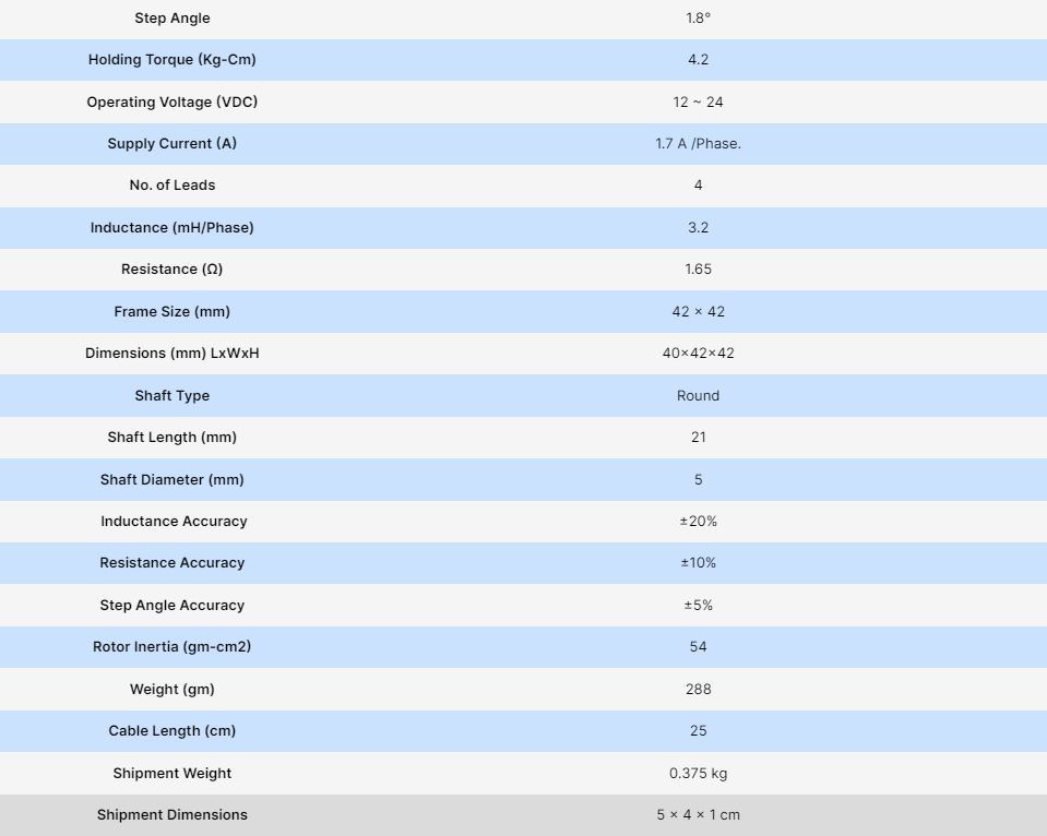
Nema 17 stepper motor
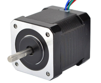
The nema 17 stepper motor is widely used in cnc machine due to quiuck response on the movement of reverse, forward and stop. This motor control
by driver. This machine give quick response on driver data. This is highly precison motor that why we seen this motor in many CNC machines.
The motor can rotate minimun 1.8 degree of rotation also. The another reason of using this motor in cnc is their Torque. This machine provide
the torque of 4.2 kg-cm at 1.7 A current. The durablity of the machine is another factor to use it.
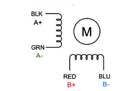
This motor have a 4 pins. There is a 2 coil are inside the motor which control its forward and backward movement. 2 wire connected with the motor's
one coil and anothe 2 wire connected to motor's second coil. This four wire are name as A+,A-,B+,B-.
The other machine details are given below-
Refrence and purchase link
Motor driver
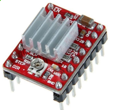
We are used A4988 motor driver to control the our stepper motor. This driver have current limiting and over current protection. We can set the current
for the motor because there is potentiometer is given on the driver. This driver control the step and direction of the motor. It has five different
step resolution. These are full step, half step , quarter step, Eigth step and sixteenth step.
In full step the motor provide low torque but smoothly rotate but in half step its torque increases. same as when we go it microstepping step resolution
we get the high torque.Other tecknical details are shown below-
Refrence and purchase link
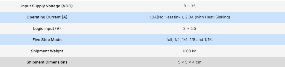
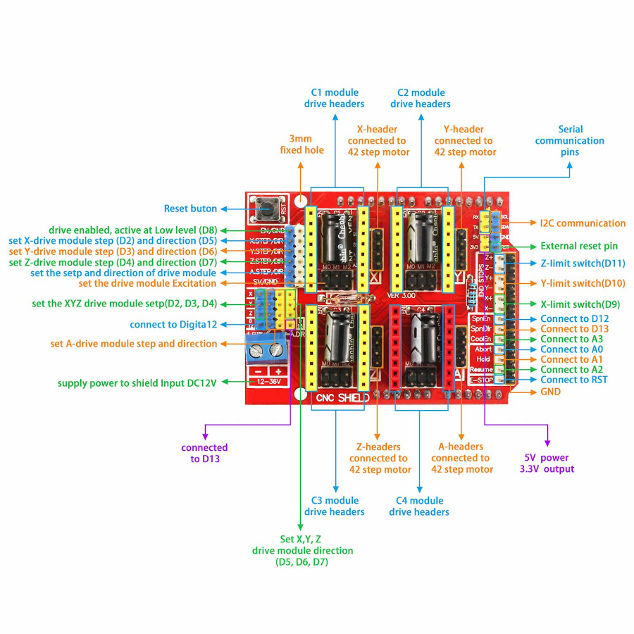
CNC shield
This shield is extension of the arduino, Means it fitted on the arduino. The pins of the shiled are connected to arduino which control or command the
motor driver to give signal to the stepper motor. This board support four driver means the it can control the 4 axis of the machine. We simply
attached the motor driver on it. It required the voltage from 12-36V DC supply Separatly. It support the GRBL firmware of version 0.9. the stepper motor are easily
connect with the given pins. We can change the direction of the motor by suffling the wire of motor with given pins in shield. This shield have many
other control like coolant control, max. length of axis control by providing limit switch, Microstepping control and spindle control.
There is pin configuration image which show the all control of the CNC shield.
Refrence and purchase link.
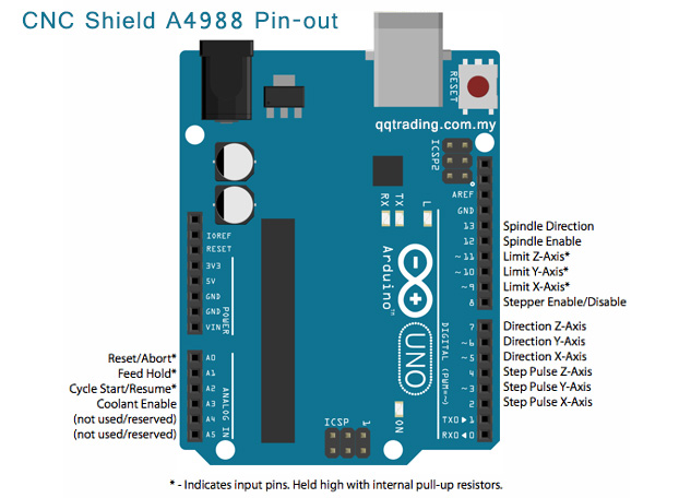
Arduino Uno
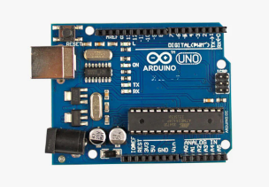
Arduino is a microcontroller system by which we can make many projects. The cnc shiels are attached on Arduino. and send the data to the cnc sheild.
the below Image show the pin used to transfer the data to cnc shield.
Component testing
Now we check the motor driver and other electronic component before assembly. The major task is that to set the current for the motor on stepperdriver by which over motor run easily. So we follow the tutorial and successfully set the current for the motor.
Refrence
Component Assembly
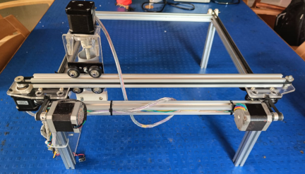
Now we start assembly of all the component of the machine. Firstly we assemble aluminium v panel and make a frame for the machine then we attachedmotor on it.
We used some 3D printed object and some laser cutting object. And after all this assembly we install the arduino UNO and cnc board on it.
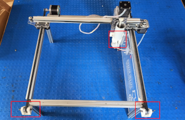
For the attachment of arduino uno we cut a acrylic sheet and then we setup the the acrylic sheet
on machine. We arrange the wiring of the machine. For the extruder part we use 50mm diameter pipe in which we assembed a push mechanism.
Y axis pulley holder are 3D printed part. X axis motor holder and pulley holder are cut on acrylic sheet of 5mm on laser cutting machine
The z axis motor holder and extruder holder is also a 3D printed part.
Firmware and Gcode Generation
Firmware
Firmware is the software which give instruction to the communication between two device. There are many firmaware which used in cnc Machines.We are going to use "GRBL" firmware which is to use. This GRBL firmware we upload in our arduino uno and then this give instruction to arduino
to communicate between cnc Shield and G code generator software. So firstly We upload the grbl file to Arduino Uno. So I Download a grbl
firmware file.
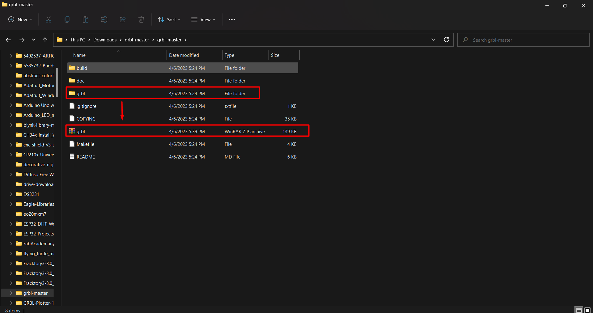
I downloaded firmware in Zip file then I extract the file. Open the extracted folder and search the file for GRBL. The folder of GRBL which
content the library for the arduino IDE. SO I convert this Particular GRBL folder into ZIp file and then I open the arduino Ide. In the arduino
ide I have to add the grbl library.
So I go to sketch and include library option. here I add the zip file of GRBL in Include Zip file option. Now GRBL library succesfully installed
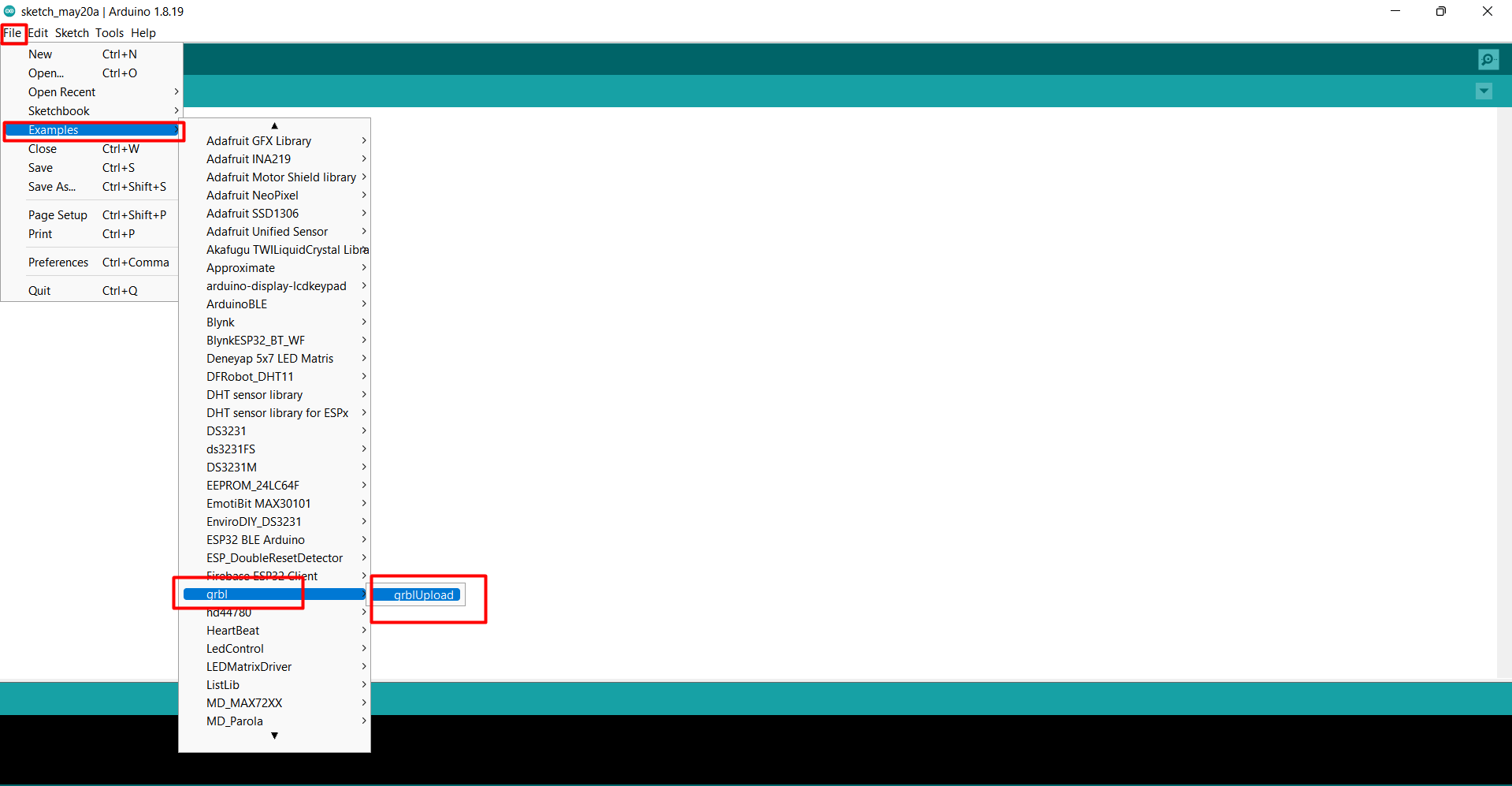
Now select file menu and go to example and search GRBL. In GRBL we get "GRBL upload" file. open this file and upload it in Arduino UNO.
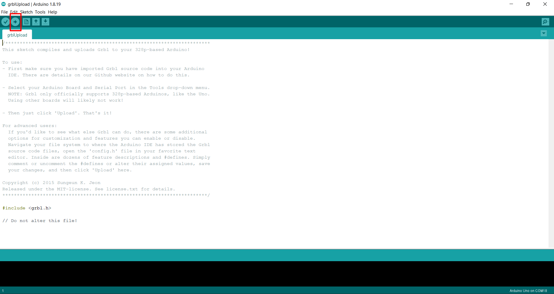
The Grbl firmware is uploaded to arduino Uno. Now we need a software which conver our file into Gcode and also calibrate our machine. So for
this I downloaded the "UNIVERSAL GCODE UPLOADER" software and install it. After The successfully installation we open the software.
We see in window machine connection option , XY and Z controlling option , Console and a visualizer which show the how our design will be
made by machine.
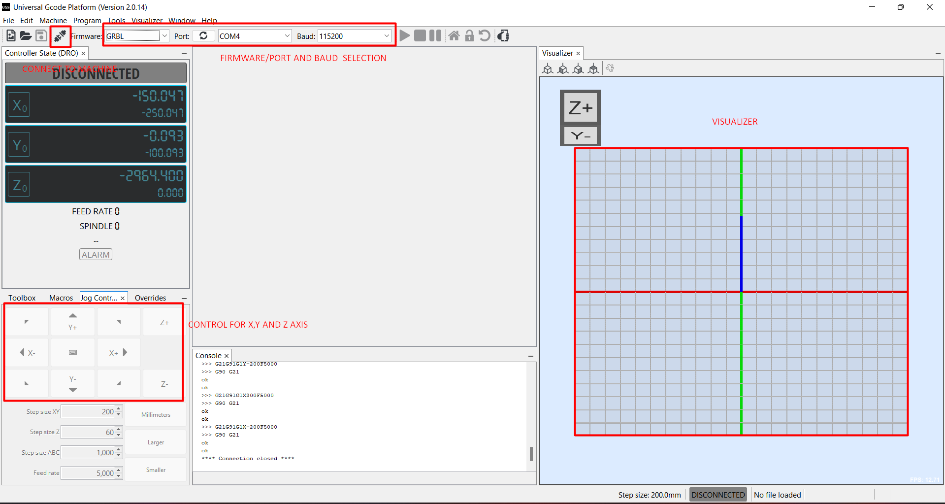
Now se;ect the firmware in my case it is GRBL , select arduino port and braud. After selection I connect the machine with click on connect
Option.
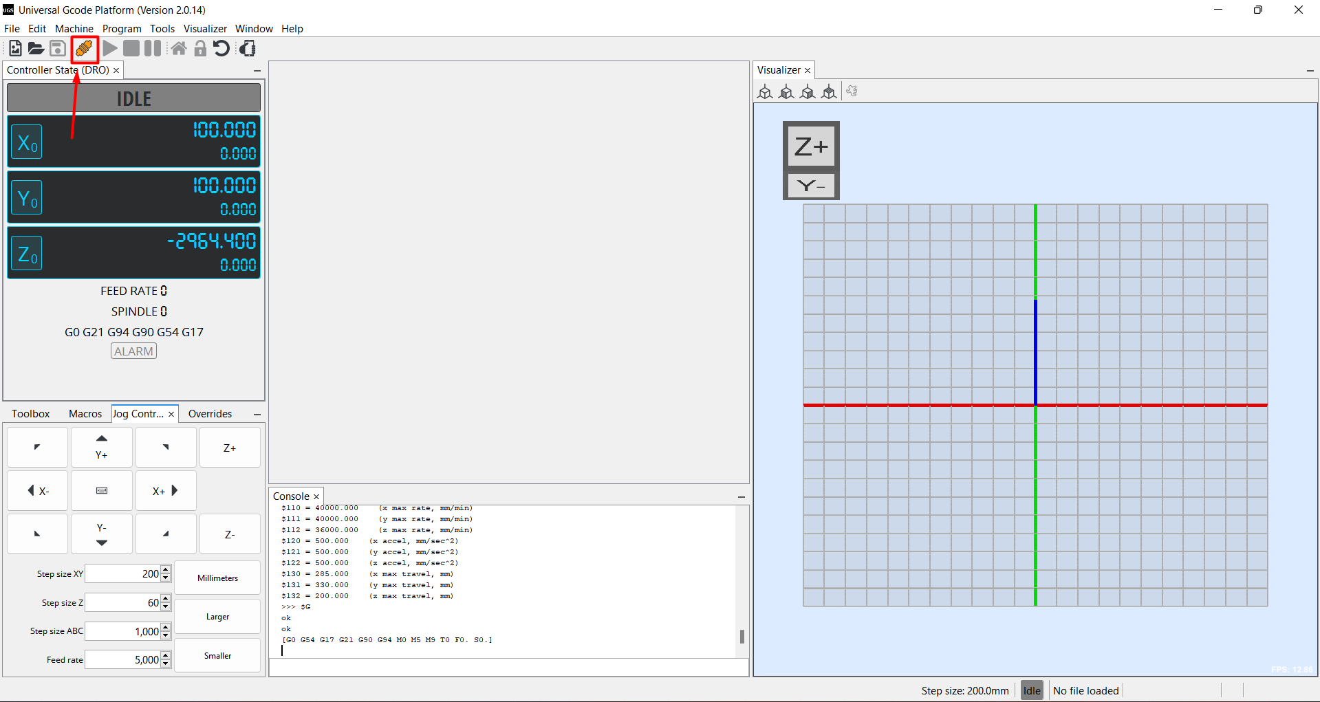
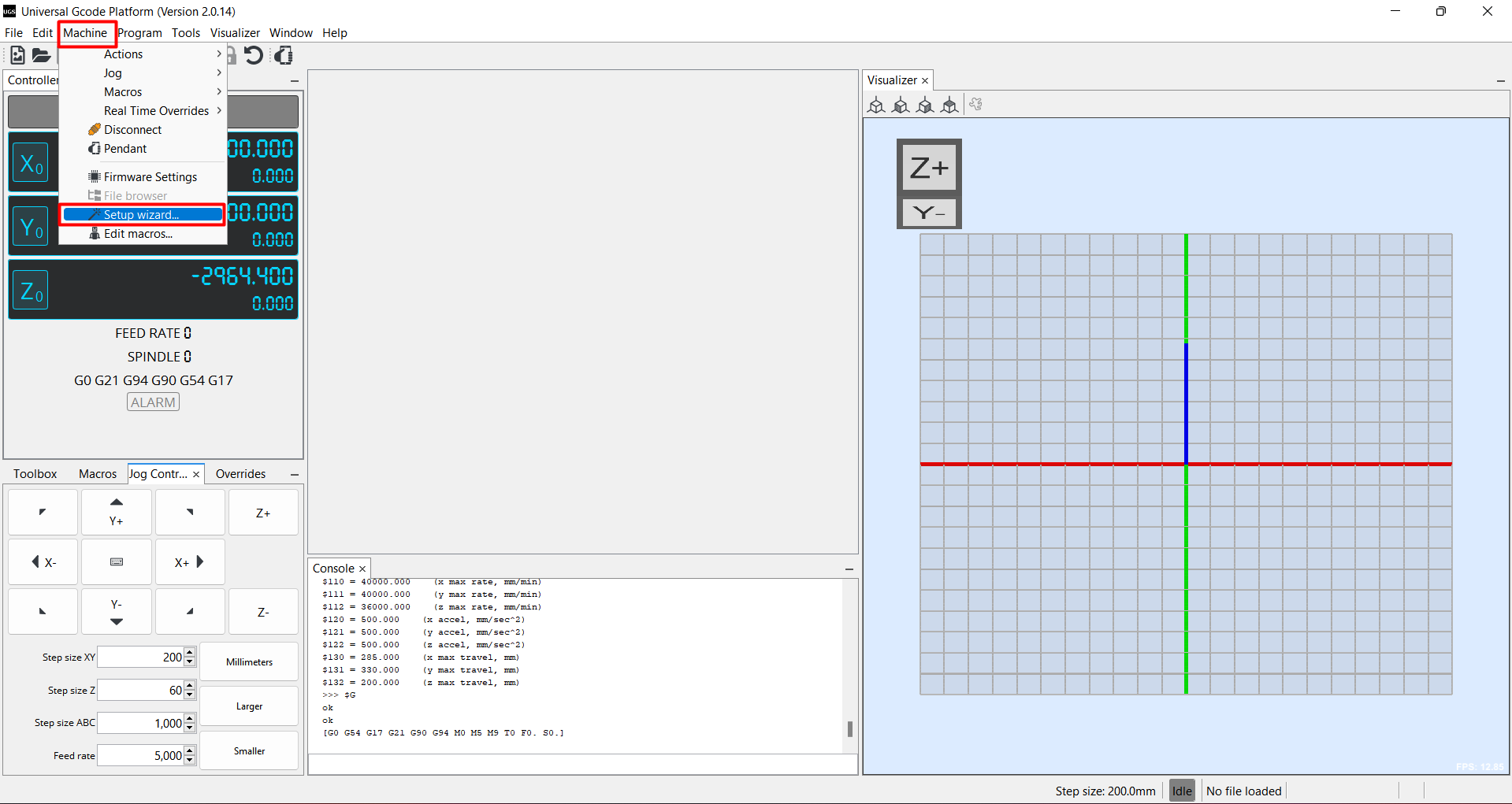
Now we have to setup the machine and have to calibrate the machine with measurements, so for this Select "Machine" option then select "Setup Wizard"
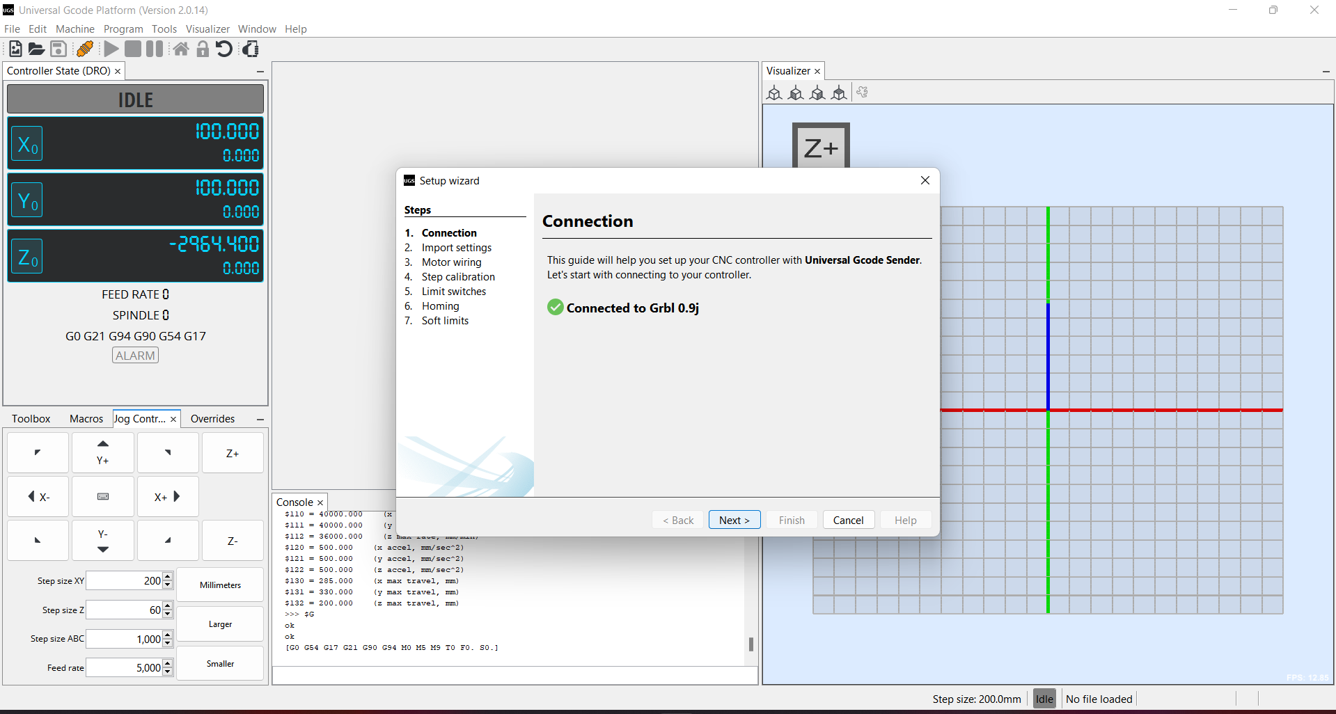
option. After that a new small window open. The first window show the connection between UGS to firmware.
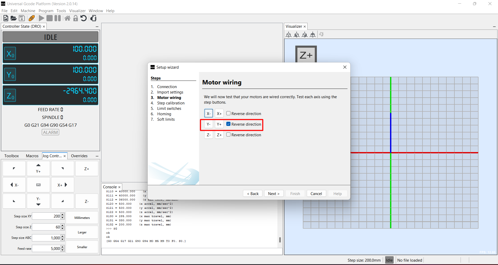
After that click on next option. In "motor wiring " option if our one of the axis rotate in reverse direction on the command of forward
So we can correct his direction. In my case I correction the rotaion direction of Y axis.
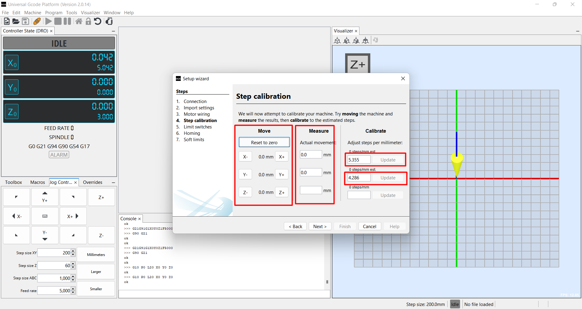
After that we calibrate the step. here we move the axis in mm and check the value in the machine how actuallt they moved. Then we enter the
value of actual movement. After that it calculate some value and this value we enter in calibrate option and update it.
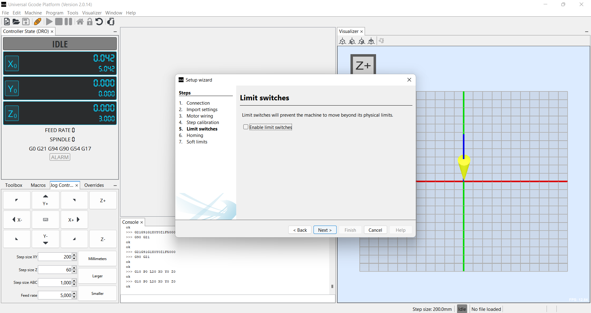
After this we get the limit switch option, you have to enable them if you want to use. We dont use the limit switch in our machine
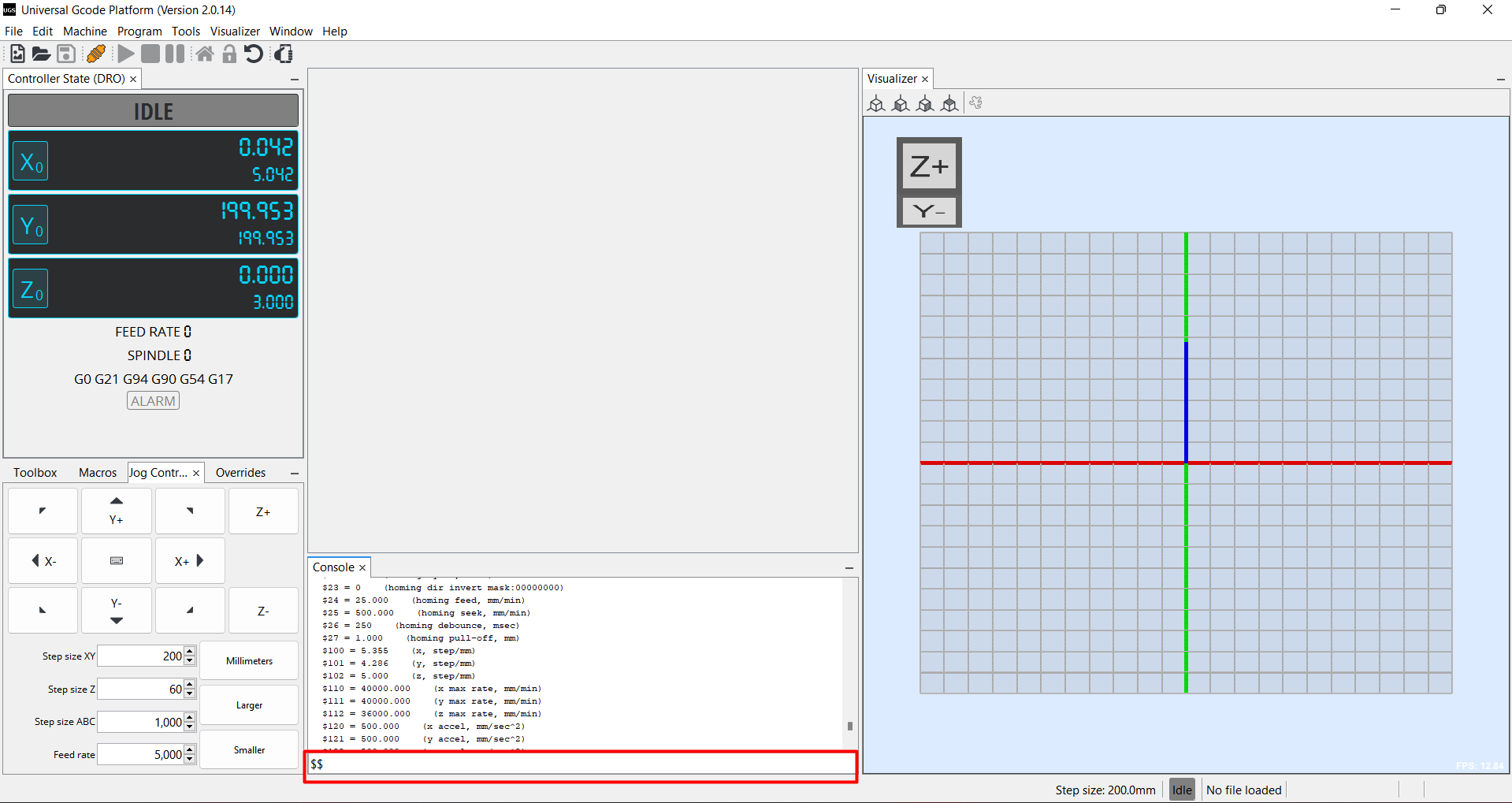
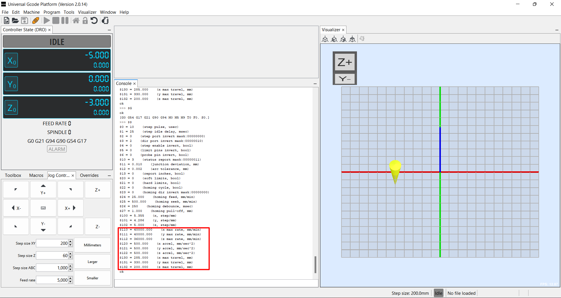
Now at the bottome we get the console section to change the value of of speed , acceleration and other parameter of axis. So for this Go search
option of console and then search "$$" after that a value menu open then copy and paste the value you want to change in console search bar. Then
change the value and click enter.
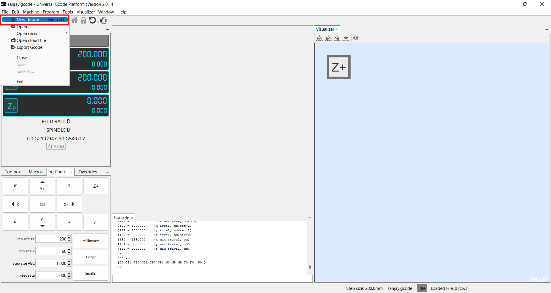
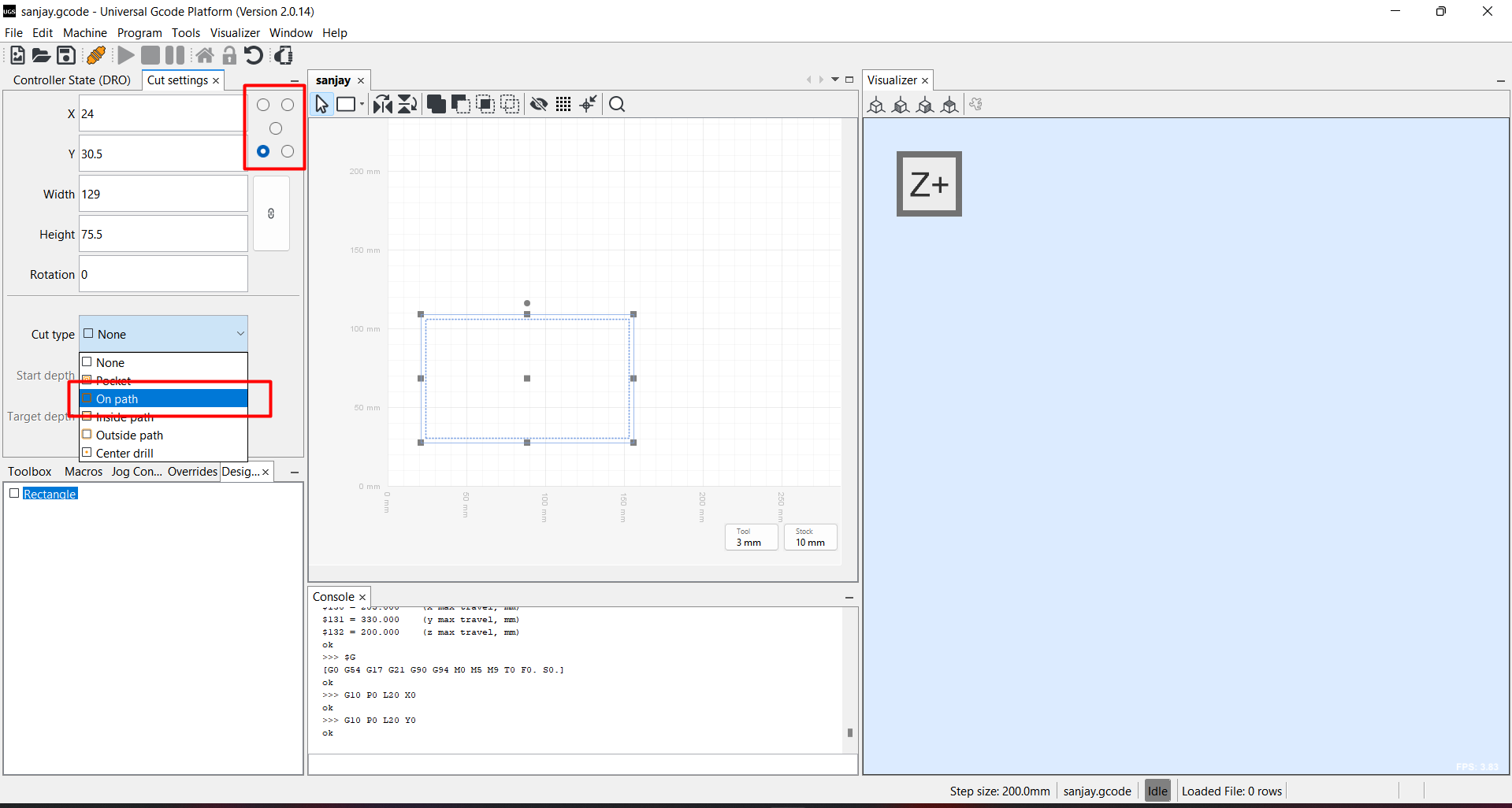
After that I go the file section and select new design and try to design a square and select path type as On path.
Testing
We test the machine by making a circular Shape Jalebi. Here is the Testing Video.Then we tried to make a rectangular Jalebi. Here is the Testing video
Final video Presentation
Learning outcomes
-I learned about CNC mechanism.-I learned about about the GRBL and G code genration for CNC.
-I design and modify the part for for machine.
-I learned about CNC shiel and stepper drivers.
Click here to download all the design file and software.
Click here to know more about group assignment.